Pierpont Morgan Library
Handi-Lift designed and installed two custom lifts for the Morgan Library and Museum, ensuring accessibility while maintaining the architectural elegance of this historic New York City landmark.
Unlock exclusive access to comprehensive solutions library and get access to the over 300+ projects
Overview
The Morgan Library and Museum, originally the private library of J.P. Morgan, is a landmark cultural institution in New York City. Founded in 1906 and opened to the public in 1924, it includes iconic designs by Charles McKim and a 2005 expansion by architect Renzo Piano. Handi-Lift, Inc. was commissioned to design and install two custom lifts—one for the Morgan Mansion and another for the Morgan Library—ensuring accessibility while preserving the architectural elegance of this historic site.
Challenge
The project involved several unique challenges:
Architectural Harmony: The lifts had to seamlessly integrate into the library’s historic and expanded spaces, complementing the stone, wood, and glass finishes.
Practicality vs. Aesthetics: Maintenance access needed to be provided without disrupting the atrium’s traffic flow or risking damage to its stone finishes.
International Coordination: The project required close collaboration with the architect in Genoa, Italy, and coordination with multiple trades over the course of more than a year.
Design & Execution
- Custom Lift Design:
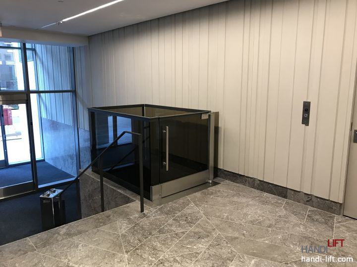
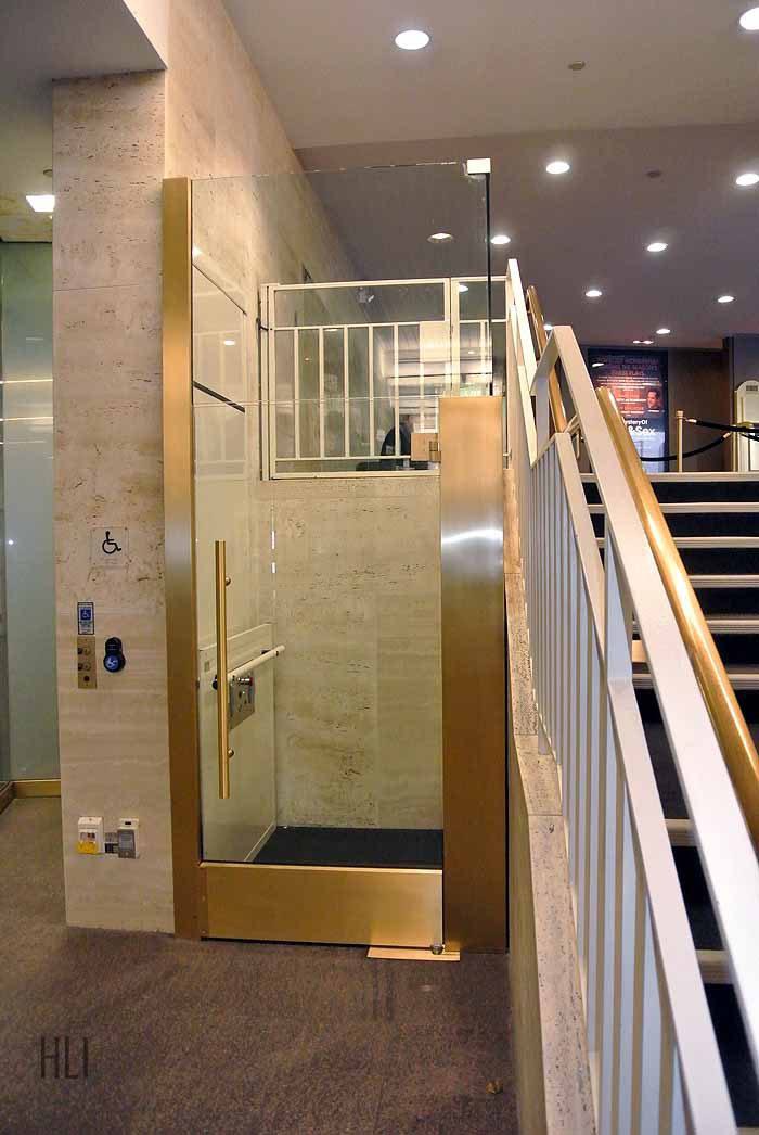
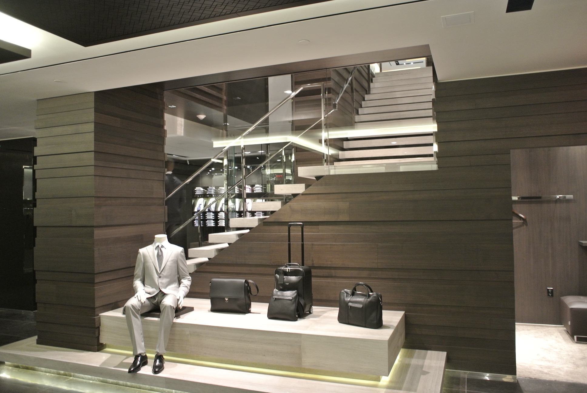
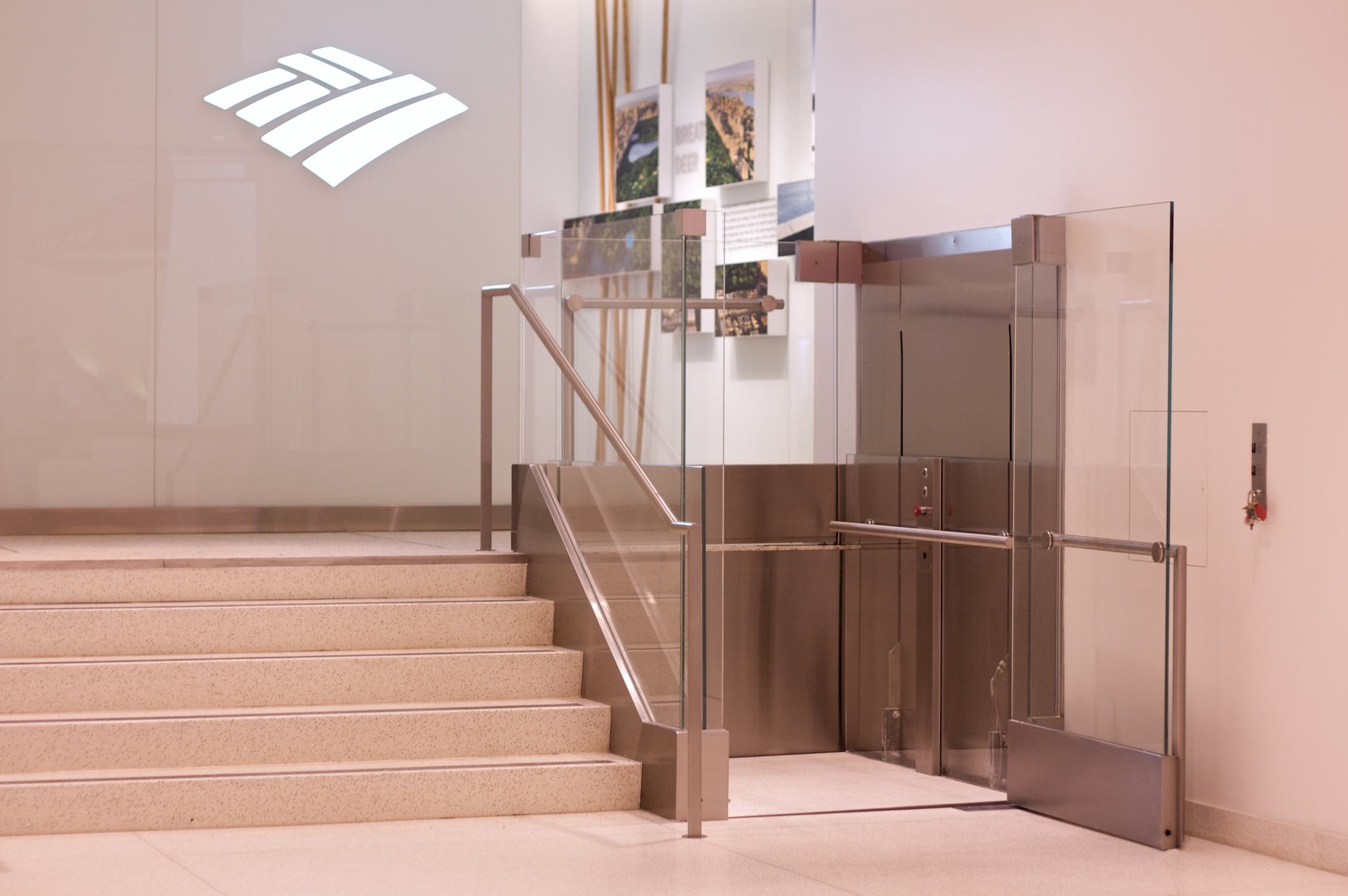
The lifts featured bare-edge glass enclosures, finished wood floors, and sawn limestone, creating the appearance of floating structures within the space.
Each lift was meticulously tailored to match the building’s architectural style, blending seamlessly with the existing design.
- Innovative Maintenance Solution:
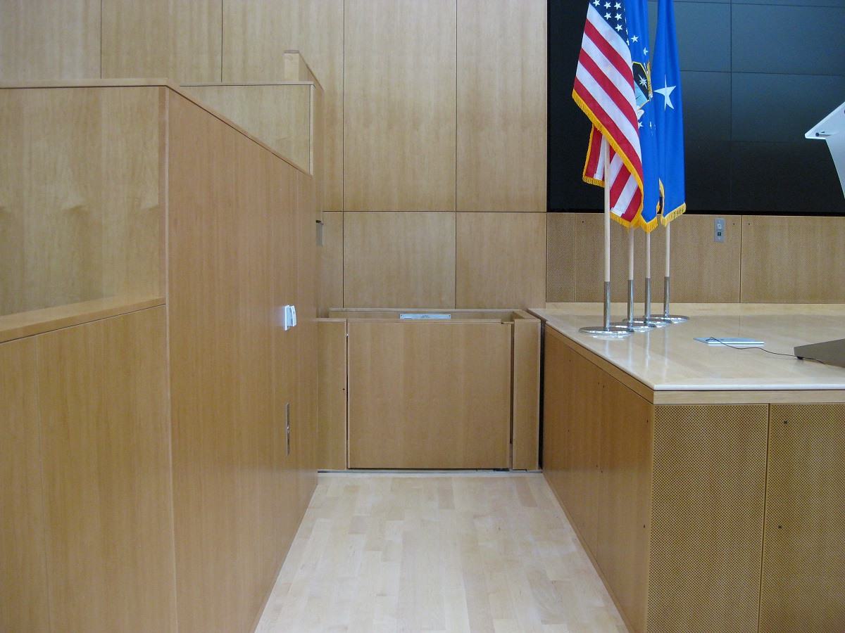
To avoid disrupting the atrium’s stonework, Handi-Lift designed a manhole in the lift’s platform floor, allowing mechanics to access the lift for service and maintenance without removing the stone skirt or altering the lobby’s finishes.
- Collaborative Approach:
The Handi-Lift team worked tirelessly for over a year, collaborating with trades and the Genoa-based architect to ensure precise execution and adherence to the building’s aesthetic and functional needs.
Results
The Morgan Library and Museum lifts are a testament to the balance of form and function:
Seamless Integration: The lifts blend so elegantly into the building’s design that they appear to float, enhancing the overall aesthetic of the spaces.
Practical Maintenance: The innovative manhole design allows for easy servicing while preserving the atrium’s finishes and minimizing disruptions.
Architectural Excellence: The project exemplifies Handi-Lift’s ability to meet high aesthetic and functional standards in a historically significant building.
These custom lifts ensure accessibility while respecting the Morgan Library and Museum’s rich architectural legacy.
Technical Specifications
-
Morgan House Lift
-
Lift System
SW-72 vertical platform lift by Garaventa, 500-pound capacity with a 5:1 safety factor, hydraulic/chain drive, 1.5 HP motor, and a speed of 20 fpm.
-
Enclosure Design
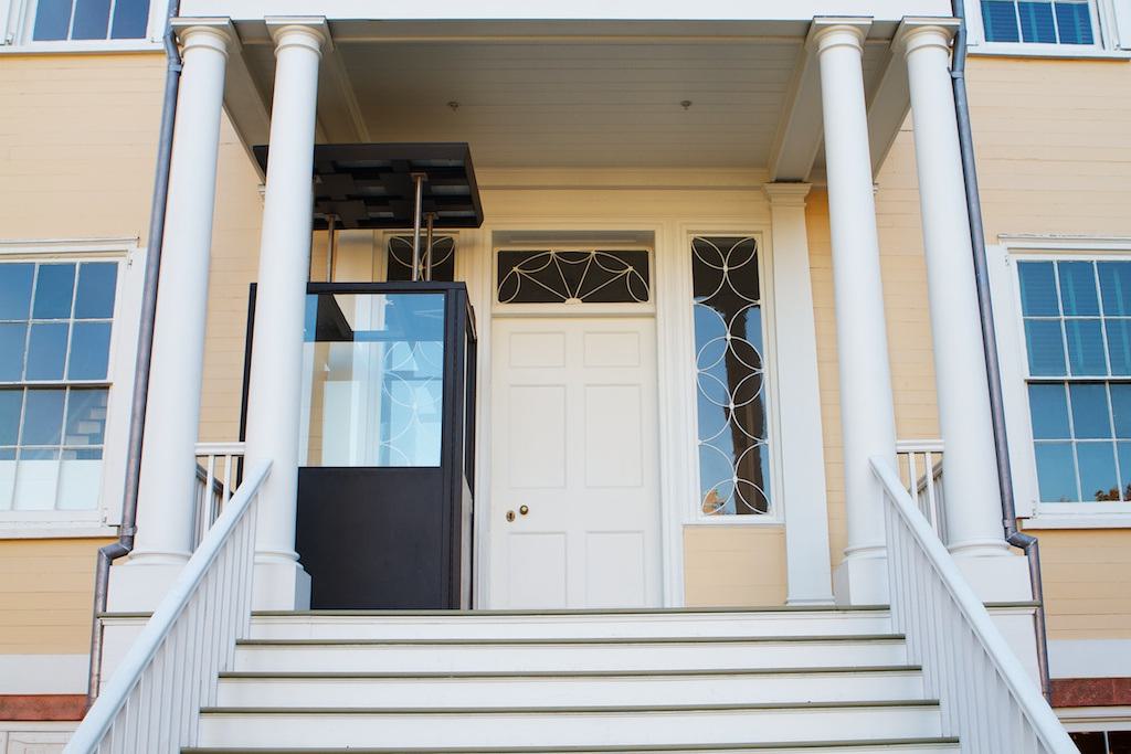
- Mast concealed within a wooden enclosure, supported by hidden brackets tied to the stair stringer.
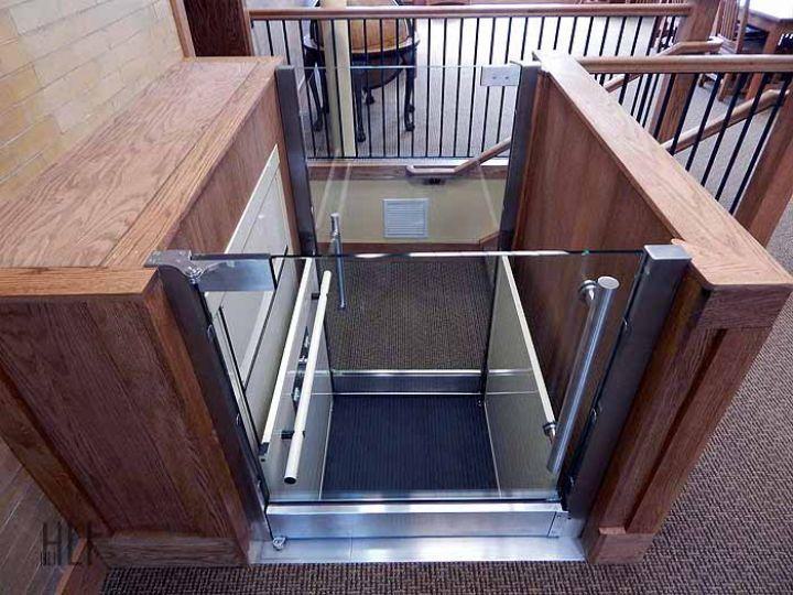
- False enclosure walls with glass platform walls featuring "bare edge" glass connected via patch hardware.
-
Platform Design
- Dual-platform configuration with a thinner top platform, allowing glass support shoes to be recessed below the finished floor, creating the appearance of floating glass panels.
- Custom car-operating station fabricated from rectangular stainless steel tubing, integrated seamlessly with the platform.
-
Door and Interlocks
- Lower door powered by an in-floor Tormax hydraulic operator, concealed beneath a removable wooden panel.
- Folger-Adams 401R deadbolt interlocks monitor door closure and locking.
-
Drive System and Controls
- Self-contained hydraulic motor pump with gravity-based lowering system.
- Microprocessor-based controls operating at 24 VDC.
- Manual lowering valve and electrical disconnect located on top of the mast for easy maintenance access.
-
Finish and Maintenance
- Stainless steel cladding with #6 finish on the mast.
- Removable car top cover and side panels for maintenance access.
-
McKim Building Lift
-
Lift System
Custom hydraulic vertical platform lift, 500-pound capacity with a 5:1 safety factor, ADA-compliant platform, and a 1.5 HP motor running at 20 fpm.
-
Enclosure and Aesthetic Design
- Glass railings integrated into the platform's design to match the surrounding architecture, with a 42-inch glass door and sidewalls.
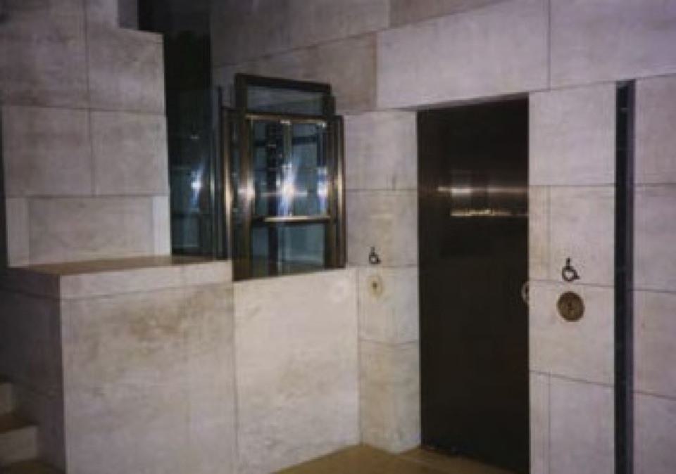
- Sawn limestone cladding on the three interior walls and under the platform, visible when the lift is at the upper landing.
-
Drive and Controls
- Direct-acting hydraulic cylinder, pump, and controller by CEMCOlift.
- Anti-creep feature and modified programmable logic controller for slow-speed constant pressure operation.
-
Platform Maintenance and Stabilization
- Removable finished wood floor with an interlocked manhole for service access to the cylinder and guide rail system.
- Swivel guide shoes beneath the platform and roller guides on two sides to maintain alignment and stability.
-
Structural and Guide Rails
- Guide rails mounted behind a cavity created by moving stone walls out 6-8 inches.
- Angle iron frame supporting guide shoes to prevent platform rotation.
-
Custom Fabrication and Integration
Entire lift system designed and fabricated to ensure seamless integration with the architectural vision while meeting safety and ADA requirements.
Location
225 Madison Avenue, New York, NY


